Microprograms
Once the configuration of a computer and its microprogrammed control unit is established, the designer's task is to generate the microcode for the control memory. This code generation, called microprogramming, is a process similar to conventional machine language programming. To illustrate this process, we present here a simple digital computer and show how it is microprogrammed.
Computer Configuration
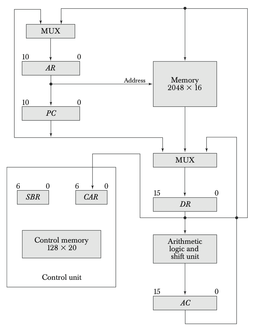
The block diagram of the computer consists of two memory units: a main memory for storing instructions and data, and a control memory for storing the microprogram. Four registers are associated with the processor unit and two with the control unit. The processor registers are:
- Program Counter (PC)
- Address Register (AR)
- Data Register (DR)
- Accumulator Register (AC)
The control unit has a Control Address Register (CAR) and a Subroutine Register (SBR). The control memory and its registers are organized as a microprogrammed control unit.
The transfer of information among the registers in the processor is done through multiplexers rather than a common bus. DR can receive information from AC, PC, or memory. AR can receive information from PC or DR. PC can receive information only from AR. The arithmetic, logic, and shift unit performs micro-operations with data from AC and DR and places the result in AC. Memory receives its address from AR. Input data written to memory come from DR, and data read from memory can go only to DR.

Instruction Format
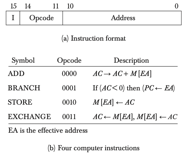
The computer instruction format consists of three fields: a 1-bit field for indirect addressing (I), a 4-bit operation code (opcode), and an 11-bit address field. Four of the 16 possible memory-reference instructions are listed below:
- ADD: Adds the content of the operand found in the effective address to the content of AC.
- BRANCH: Causes a branch to the effective address if the operand in AC is negative.
- STORE: Transfers the content of AC into the memory word specified by the effective address.
- EXCHANGE: Swaps the data between AC and the memory word specified by the effective address.
Each computer instruction must be microprogrammed. Only four instructions are considered here to simplify the microprogramming example.
Microinstruction Format
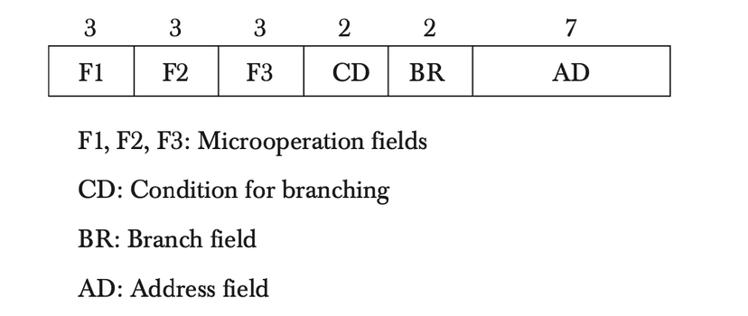
The microinstruction format for the control memory is divided into four functional parts: three fields (F1, F2, and F3) specify micro-operations for the computer, the CD field selects status bit conditions, the BR field specifies the type of branch to be used, and the AD field contains a branch address. The address field is seven bits wide, since the control memory has 128 words.


Microinstruction Fields and Codes
| Field | Binary Code | Microoperation Symbol | Description |
|---|---|---|---|
| F1 | 000 | NOP | No operation |
| 001 | ADD | ||
| 010 | CLRAC | ||
| 011 | INCAC | ||
| 100 | DRTAC | ||
| 101 | DRTAR | ||
| 110 | PCTAR | ||
| 111 | WRITE | ||
| F2 | 000 | NOP | |
| 001 | SUB | ||
| 010 | OR | ||
| 011 | AND | ||
| 100 | READ | ||
| 101 | DRTAC | ||
| 110 | INCDR | ||
| 111 | PCTDR | ||
| F3 | 000 | NOP | |
| 001 | XOR | ||
| 010 | COM | ||
| 011 | SHL | ||
| 100 | SHR | ||
| 101 | INCPC | ||
| 110 | ARTPC | ||
| 111 | - |
Condition and Branch Fields
| Field | Binary Code | Symbol | Condition |
|---|---|---|---|
| CD | 00 | U | Unconditional |
| 01 | I | Indirect Address | |
| 10 | S | Sign Bit of AC | |
| 11 | Z | Zero in AC | |
| BR | 00 | JMP | Jump |
| 01 | CALL | Call Subroutine | |
| 10 | RET | Return from Subroutine | |
| 11 | MAP | Map Opcode to CAR |
Symbolic Microinstructions
A symbolic microprogram can be translated into its binary equivalent by means of an assembler. Each line of the assembly language microprogram defines a symbolic microinstruction. Each symbolic microinstruction is divided into five fields: label, microoperations, CD, BR, and AD.
Fetch Routine
The fetch routine consists of three microinstructions, which are placed in control memory at addresses 64, 65, and 66:
PCTAR- Transfer the address from PC to AR.READ, INCPC- Read the instruction from memory into DR, and increment PC.DRTAR- Transfer the address part of the instruction from DR to AR and map the opcode to CAR.
Symbolic Microprogram
ORG 64
FETCH:   PCTAR                   U   JMP   NEXT
         READ, INCPC             U   JMP   NEXT
         DRTAR                   U   MAP
Binary Microprogram
| Address | Binary Microinstruction |
|---|---|
| 1000000 | 110 000 000 00 00 1000001 |
| 1000001 | 000 100 101 00 00 1000010 |
| 1000010 | 101 000 000 00 11 0000000 |
Microinstruction Routines
Here are the microinstruction routines for the four computer instructions:
-
ADD Instruction:
ORG 0 ADD: NOP I CALL INDRCT READ U JMP NEXT ADD U JMP FETCH -
BRANCH Instruction:
ORG 4 BRANCH: NOP S JMP OVER NOP U JMP FETCH OVER: NOP I CALL INDRCT ARTPC U JMP FETCH -
STORE Instruction:
ORG 8 STORE: NOP I CALL INDRCT ACTOR U JMP NEXT WRITE U JMP FETCH -
EXCHANGE Instruction:
ORG 12
EXCHANGE: NOP                      I   CALL   INDRCT
          READ                     U   JMP    NEXT
          ACTOR, DRTAC             U   JMP    NEXT
          WRITE                    U   JMP    FETCH
Indirect Subroutine (INDRCT)
The indirect subroutine handles the indirect addressing mode:
ORG 67
INDRCT:   READ                       U   JMP    NEXT
          DRTAR                      U   RET