Shift Microoperations
Shift microoperations are integral to the serial transfer of data within a computer system. They are employed in conjunction with arithmetic, logic, and other data-processing operations. By shifting the contents of a register either to the left or to the right, data can be transferred and manipulated efficiently.
During a shift-left operation, the bits in the register are shifted left, and the rightmost bit receives its new value from the serial input. Conversely, during a shift-right operation, the bits are shifted right, and the leftmost bit is updated from the serial input. The nature of the serial input bit determines the type of shift: logical, circular, or arithmetic.
Logical Shift
A logical shift transfers a zero through the serial input. The notation shl represents a logical shift-left, and shr represents a logical shift-right. For example:
R1 ← shl R1specifies a 1-bit logical shift to the left for the content of registerR1.R2 ← shr R2specifies a 1-bit logical shift to the right for the content of registerR2.
In these operations, the register symbol must appear on both sides of the operation. During a logical shift, the bit entering the register through the serial input is always zero.
Circular Shift
A circular shift, also known as a rotate operation, rotates the bits of a register around both ends without any loss of information. This is achieved by connecting the serial output of the shift register to its serial input. We use cil for circular shift-left and cir for circular shift-right. The operations can be represented as:
R ← cil Rfor a circular shift-left.R ← cir Rfor a circular shift-right.
Arithmetic Shift
An arithmetic shift is used for shifting signed binary numbers. An arithmetic shift-left (ashl) multiplies the number by 2, while an arithmetic shift-right (ashr) divides the number by 2. Importantly, the sign bit must remain unchanged to preserve the number's sign.
The leftmost bit in a register (sign bit) remains unaffected during an arithmetic shift:
R ← ashl Rrepresents an arithmetic shift-left.R ← ashr Rrepresents an arithmetic shift-right.
Detailed Operation of Arithmetic Shift
Consider a register with n bits, where is the sign bit:
- Arithmetic Shift-Left (ashl): Shifts all bits to the left, inserts a 0 into the least significant bit (LSB) and might result in overflow if the sign bit changes:
- Arithmetic Shift-Right (ashr): Shifts all bits to the right, preserving the sign bit:
If an arithmetic shift-left operation results in a sign bit change (which indicates overflow), an overflow flip-flop (V) is used to detect and handle this overflow:
Hardware Implementation
A shift unit can be implemented using a bidirectional shift register with a parallel load. Data can be loaded into the register in parallel and then shifted either to the left or the right. This setup requires a clock pulse for loading data and another pulse for shifting.
For efficiency, especially in processors with many registers, a combinational circuit for the shift operation is preferred. This approach uses a common bus to transfer data to a combinational shifter, which then shifts the data before loading it back into the register, requiring only one clock pulse.
Combinational Circuit Shifter
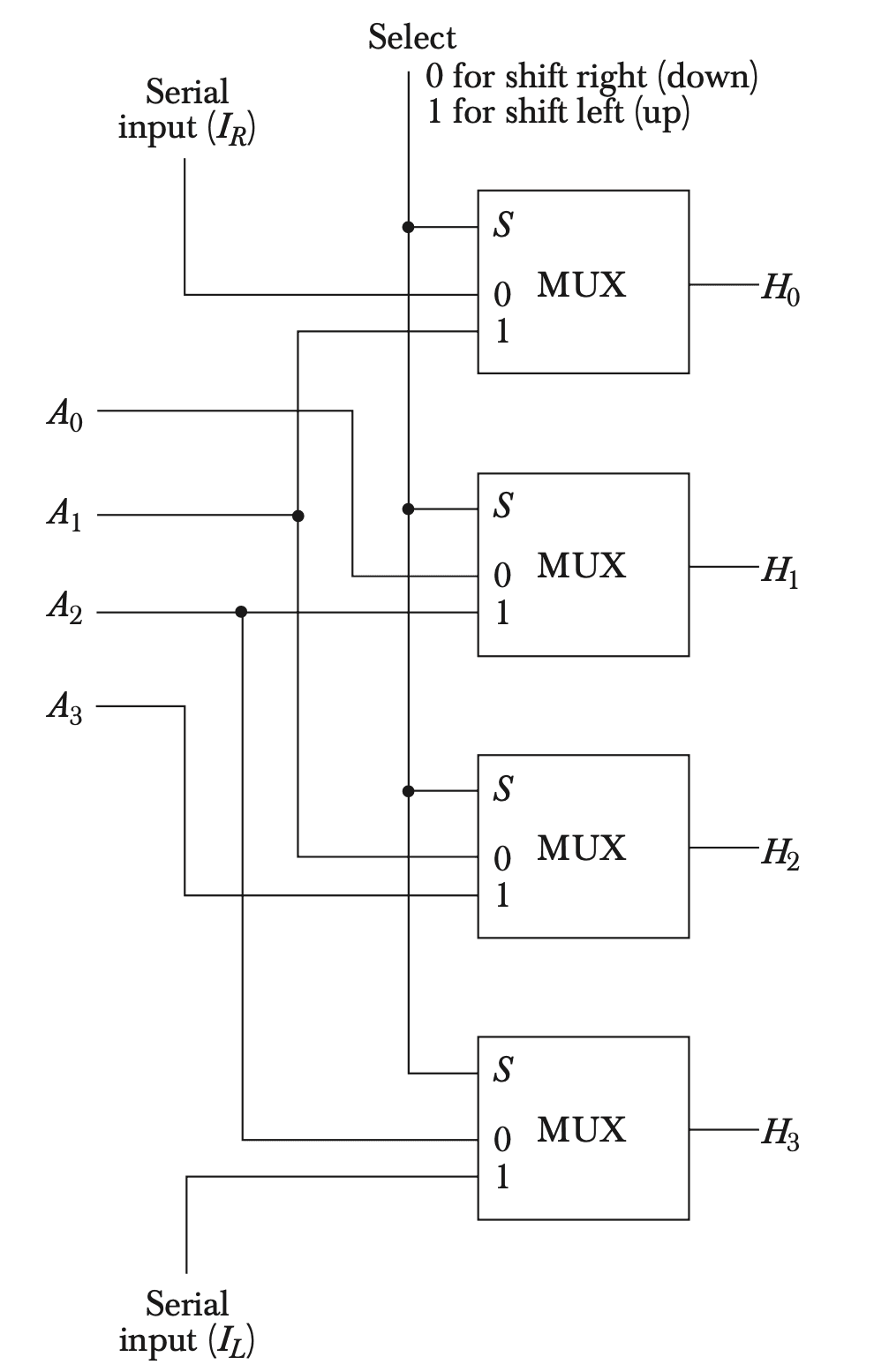
A combinational circuit shifter can be constructed using multiplexers. For example, a 4-bit shifter has four data inputs ( through ) and four data outputs ( through ). It includes two serial inputs for shift-left (IL) and shift-right (IR) operations. The selection input (S) controls the direction of the shift:
- When , data is shifted right.
- When , data is shifted left.

Function Table of the Shifter
The following table shows the input-output mapping based on the selection input (S):
| S | Output | Output | Output | Output |
|---|---|---|---|---|
| 0 | IR | |||
| 1 | IL |
For an -bit shifter, multiplexers are required. Another multiplexer can control the two serial inputs to provide logical, circular, or arithmetic shifts.